Choose the Right Sanding Method
Negotiable Min Order Quantity Unit
- Required Quantity
-
- Place of Origin
- Payment Terms
- Negotiable
- Production method
- Negotiable
- Shipping / Lead Time
- Negotiable / Negotiable
- Keyword
- Category
- Other Machinery & Industry Equipment

A-Tech Ltd.
- Verified Certificate
-
17


| Product name | Choose the Right Sanding Method | Certification | - |
|---|---|---|---|
| Category | Other Machinery & Industry Equipment | Ingredients | - |
| Keyword | - | Unit Size | - |
| Brand name | - | Unit Weigh | - |
| origin | Stock | - | |
| Supply type | - | HS code | - |
Product Information
| Choose the right sanding method
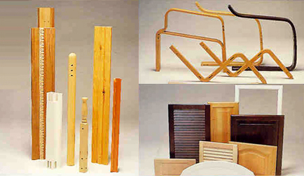
It is well-known fact that a wooden surface becomes rough after sealing. The reason for this is that fime fibres are created by ordinary wood sanding procedures, for instance using a widebelt sander.
Because of the pressure of the abrasive material against the surface, the wood's fibres are severed, resulting in microscopic fibres creating a 'fuzzy' surface. During the following sealing process, tension is generated in the fibres causing them to rise, and thereby giving the surface a rough feel.
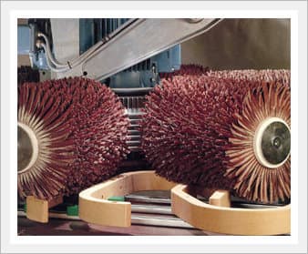
In other words wo need to look at the fibres! The presence of these fibres must be minimised of efficiently removed before of after the sealing process. The solution is to use the FLADDER sanding system - an innovative sanding method based on sanding principles which are fundamentally different from those of traditional sanding methods.
Rather than sanding with a constant pressure against the surface, the FLADDER sanding system is based on a principle by which the sanding aggression is created by the sanding tool's rotating speed.
Figures A and B show a wooden surface sanded in the nomal way before and after sanding with the FLADDER sanding system. When it comes to choosing the right sanding method there are a nomber of choices, deponding on the desired quality - and of course the allowed budget!
The figures on the left show simplified illustrations of the different sanding methode: spindles are shown with arrows indicating the rotating direction, a dark blue arrow marks the fibre's direction, and the part for sanding is shown with profiles or recesses marked A and B.

-. Figure 1
Shows a very simple sanding technique: 2 counter-rotating spindles.
As a result, part of the sanding action goes slong the fibres, and part of it goes across the fibres. In many cases this is a sensible and economical solution, but it is very likely that the A and B profiles will not be uniformly sanded, as the sanding action is performed along the A profile and across the B profile.
It is, however, possible to improve this method by feeding the part into the machine at an angle. However, the wear on the sanding tool will always be uneven, with a tendency for the spindles to wear down most quickly at the middle.
1. Parallel spindles - counter-rotating.

-. Figure 2
This is a slightly improved method: The part is sanded in an orbital movement by 6 spindles, all however rotating in the same direction, say, counterclockwise. The result is a more uniform sanding of the A and B profiles on the part. In addition, there is an even wear on the sanding tool.
However, as appears also from the illustration, the left half of the part will be sanded in one direction, and the other half in a differeant direction. This means that the fibres on one half are likely to be merely pressed down ahainst the surface, because the sanding action goes along, rather than against, the fibres.
2. Rotating spindles - rotating in same direction.

-. Figure 3
Shows a more perfect method of sanding: The part is sanded in an orbital movement, but this time with 6 spindles arranged in 3 pairs of counter-rotating spindles. The entire surface of the part is now uniformly sanded, as well as the A and B profiles.
This is the principle used in the FLADDER sanding system which has been successfully introduced in numerous companies throughout the world!
3 Rotating spindles - counter-rotating.

-. Figure 4
Shows a refined version of the above principle used in the FLADDER sanders: The part is now sanded in both an orbital and an oscillating movement with 6 spindles arranged in 3 pairs of counter rotating spindles.
As a result of the added oscillating movement it is possible for intance to feed the parts through the machine side by side, and still be certain that they will be uniformly sanded. This oscillating method is required for sanding in, say, an automatic finishing line.
4. Rotating spindles - counter-rotating and oscillating.



B2B Trade
| Price (FOB) | Negotiable | transportation | - |
|---|---|---|---|
| MOQ | Negotiable | Leadtime | Negotiable |
| Payment Options | Negotiable | Shipping time | Negotiable |

- President
- Kim, Soung-eun
- Address
- 178-2, Suyu-dong, Gangbuk-gu, Seoul
- Product Category
- Other Machinery & Industry Equipment
- Company introduction
-
A-Tech was established on first of June in 1999. We mainly deals in optical instruments like Microscope, endoscope, LCD Projector etc and measuring instruments like Data logger, thermometer, metal processing instruments etc and lab instruments like image processor etc.
We do business with laboratory, university, quality control department so our items are suitable for field to need precision.We have been providing domestic buyer with grinding machine of Fladder Co. in Denmark
That product is 3D processing machinery so you could apply our goods to precision manufacturing like aircraft, metal processing, and plastic, wood processing.
Thank you very much.
- Main Product
Related Products
,_Smartphone_dryer,_heating_mobile_2.jpg)
Mobile Dryer, Smartphone dryer, heating chamber(RG-202)
AIRLESS PUMP- YL 731
Small Sirocco Fan(TIS-190FS, TIS-190FT)
AIS3000 HD
Date Pin (Date Core)


 South Korea


